Assembly Information
Some are intimidated by the part count of large antennas, and our LPDAs are no exception. However, the process is straightforward and intuitive if the instructions are followed, in order and without substitution.
One key thing to keep in mind… the hot-boom LPDA is NOT a yagi!
Unlike most horizontal element arrays where the elements are insulated, the term “hot-boom” refers to the fact that the boom is energized and is in fact an integral part of the feedline. A balanced line of sorts, where spacing between the booms and element placement are critical for proper operation.
The key mistake made by some assemblers is that they do not pay attention to the proper phase orientation when assembling the booms and the root element segments. If this mistake is avoided, the rest of the assembly is easy.
Click on a topic to jump to the desired section
Element Orientation and Assembly
Shorting Stub – Why is it Necessary?

Element Orientation and Assembly
Incorrect Element Placement
Look closely at the top and bottom boom and you will notice that all elements on each boom are facing the same direction. This is incorrect and will not provide the proper phase orientation for each pair in the array.

Understanding that the top and bottom booms are a mirror image of one another in important.
Therefore, both booms should be assembled in an identical fashion, with boom markings and hardware facing up and each element root oriented in the same direction, alternating left and right.
Once this is complete, one of the booms can simply be flipped, creating the correct alternating phase orientation.
Pay particular attention to the solid black lines below. This is how both booms should be built. The dotted lines represent the lower boom once it’s flipped.

Correct Element Placement
Look at the image below and you’ll notice that the elements alternate left/right and top/bottom (green arrows).
This is correct for a hot-boom design.

Recall the term “hot-boom” and the relationship between the top and bottom. Given that these two parallel tubes are a balanced feedline for the elements, all are driven elements. Nothing should exist between the booms and all fastening hardware will protrude from the top of the top boom and the bottom of the bottom boom.
It really does make better sense with a manual and parts in hand. Rest assured, it’s all fairly intuitive.
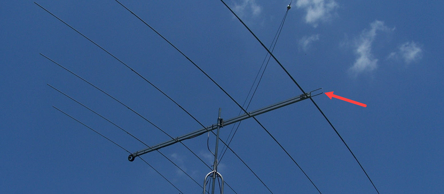
Shorting Stub - Why is it Necessary?
The booms of the Tennadyne LPDA have a natural resonance that often lands in the 12m Amateur Band.
The shorting stub acts to “lengthen” the boom and shift this resonance to a lower frequency so it doesn’t interfere with Amateur ham bands, MARS, SHARES, Civil Air Patrol or other service’s normal operating frequencies.
Some incorrectly refer to this component as a “tuning stub”, which is incorrect as it doesn’t serve to tune anything, it only serves to shift the boom’s electrical length.
Collins-style Common-Mode-Choke
Tennadyne recommends the use of the Collins-style CMC choke assembly (shown below). While other baluns and matching assemblies have been used with mixed reviews, the simple Collins choke is best suited for Tennadyne’s hot-boom design. Each boom is fed directly at the front with 50-ohm feed line (center conductor and shield), and while there are many theories about how the hot-boom design requires special care in routing the feedline, our testing demonstrated no adverse effect when using our recommended method. In fact, the simplest and most durable solution proves to be the best suited for our LPDA. The founder of Tennadyne and designer of our LPDA product line conducted several field strength tests and came to the following conclusions.
Test Conditions
Test 1 – Placed choke at feed point of antenna and routed feedline along the bottom of the lower boom section.
Recommended configuration – Zip ties or electrical tape may be used to secure the coax along the lower boom, but no conductive material should be placed between the booms as they are an integral part of the feed line circuit and spaced for proper impedance.
Test 2 – Placed choke at feed point of test antenna and allowed feedline to drape down and away towards the mast.
This configuration destroyed the F/B as the outside of the feed line picked high levels of RF.
Test 3 – Placed choke at the feed point and dressed the feedline on plastic spacers 15” below the lower boom.
While an improvement over test #2, this configuration also picked up higher levels of RF than test #1.
Conclusion
Balanced open-wire feedlines essentially do not radiate. Therefore, the twin booms of our antennas, which are certainly a balanced open-wire feedline, do not radiate. This was amply demonstrated during testing. The purpose of a common-mode current choke is to remove as much RF as is possible from the outside of the feedline and is thus the rationale to place it at the feed point of the test and production antennas. The placement of the common-mode current choke at the feed point, and attaching the feedline directly beneath the lower boom of the antenna, does a very admirable job of removing current from the outside of the feedline. There doesn’t appear to be a need for a second balun at any other point in the same feedline. It is further believed that the lower boom may act to effectively shield the coax from RF energy radiating from the nearby elements.
Installation
Whether you are using our high-quality LPDA Choke assembly or winding your own, prepare and install as shown in the photo below. Center conductor should be connected to the upper boom and the shield to the lower (red arrows).

Clean and Lubricate to Prevent Galling
Galling can be the most frustrating part of using stainless steel hardware and can even cause the threads to completely seize, sometimes to the point of no-return!
Galling is a form of wear due to excessive friction between two moving surfaces. This can happen when installing a bolt into a threaded hole, such as the nylon lock nuts that are shipped with our kits.
Severe galling can result in the parts becoming so seized that the part is no longer removable. This term is known as “cold welding” since the materials don’t heat up very hot, but act like they have welded together.
– – – – –
The smaller SS hardware used to fasten elements into place isn’t typically a problem as they only need to be snugged, not torqued, to avoid deforming the tubes.
However, all 3/8-16 SS hardware used on the Boom-to-Mast and Slipp-Nott assemblies should be cleaned of any debris and lubricated to prevent galling.
All of our kits ship with C5-A Anti-Seize, which should be liberally applied to the 3/8″ SS hardware to prevent galling.
